| M4 & M4A1 w/T1E3 Mine Exploder | UniModel Kit #370 & 221 |
| Article by Stephen Brezinski; last updated 17 November 2012 | |
  |
|
| Modeling the Sherman Tank in 1/72nd Scale |
| M4 & M4A1 w/T1E3 Mine Exploder | UniModel Kit #370 & 221 |
| Article by Stephen Brezinski; last updated 17 November 2012 | |
|
|
| The Sherman tank and its brother
M3 Medium and Canadian Grizzly tanks are among my
favorite AFVs to model. I cannot think of another
AFV that has so many variants to model; I mean multiple
roadwheel and sprocket variations, three major turret
types, four different main guns, three major suspension
types all with minor variations, a dozen track types,
four totally different engines, etc. And this
covers just the WW2 models of the Sherman. Along
with Trumpeter and Dragon’s Sherman kits released
over the recent years, Unimodels also has released a near
full line of M4 variants including specialized
“Funnies” mounting rocket launchers and mine
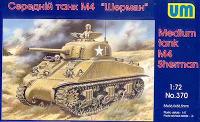
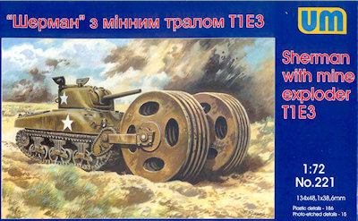
rollers, such as kit number 221 reviewed below. Okay, lets dissect these kits. The Box Art, What is Supposed to Be in the Box The box art for UM’s M4A1 kit shows the cast hull tank pushing a T1E3 “Aunt Jemima” mine roller that would cause a buried mine to detonate under the roller rather than the tank track. The soft rounded edges of the cast hull are clear. The hull and turret have no appliqué armor plates typical of mid-wartime Shermans. There are no direct vision view ports in front of the driver and co-driver hatches but the front is still the early 47 degree slope glacis with small hatches for the driver and co-driver. The track type and return roller style I cannot identify but the (Vertical Volute Spring Suspension) bogies have the offset return roller. The single, split hatch on the cast turret for the commander is open but no commander is shown. The gun mantlet, also called a rotor shield, is the initial, early type without the little rectangular wings on the side of the 75-mm barrel (to inhibit bullet splash I have read). The lifting rings portrayed are at the far top edge of the gun mount which I have read indicates that it is not the initial type of gun mount or that it has been field modified. The T1E3 roller portrayed looks reasonably accurate including the sprockets and chain drive going back to the tank’s sprocket wheel. From historical photos this mine roller was deployed with both M4 and M4A1 Shermans. The tank in the painting is finished in just olive drab with white stars, no serial number or unit identification. Here we have UM’s nice box art showing a radial engine, welded-hull M4 tank with mixed features. The direct-vision driver and co-driver vision viewports, no appliqué armor on the hull sides and in front of the driver and co-driver hoods, and the open spoke roadwheels tell me it is an early construction of 1942 or early 1943 (the “hoods” are the protrusions on the upper glacis that the hatches cover. The fold-up direct vision viewports is a particularly nice feature. In the beginning thousands of these Sherman type were produced but it is rare to find the feature in a model kit. I think by 1943 most of these had an appliqué armor plate on the front of the two hoods covering up the visor. Down the edge of the 47 degree front, glacis, armor plate we see a weld seam joining it with the side plate. Many early M4’s had a glacis constructed of smaller armor plates connected into one plate by vertical and horizontal welds; on this M4 I see a horizontal weld line from visor to visor but no vertical weld. . The wide M34A1 gun mantlet and one-piece transmission cover (the round nose) indicates later construction. The gunners side (our right) side of the mantlet seems to have two holes. The higher hole nearer the gun I believe is a screw hole like those just above the gun barrel. There is a commander sticking out of the turret’s single cupola and split hatch. This single hatch is also common to the early Sherman manufacture. I cannot give exact dates as to introduction of these features as I understand there was much mixing due to repairs, rebuilds and last delivered first used of factory parts. Along the side of the hull superstructure is a horizontal strip of sheetmetal with holes for mounting the side sand skirts to keep dust down. Most US Shermans did not use the side sand skirts. This strip of metal and holes is not included in the kit. The chevron tread pattern on the track looks too narrow to be rubber T48 track but not the correct shape for the all steel track T-54 or T-74 block. This is also discussed at Doug Chaltry’s review of this model kit at http://www.172shermans.com/kitreviews/UM/M4_prev.htm . The sprocket wheels on the VVSS (Vertical Volute Spring Suspension) bogies at the front looks to be a “fancy” sprocket type of sprocket. The roadwheels are the open spoke style The tank is painted in a single olive drab color with a single white star marking, no serial number, vehicle name or number and no additional camouflage colors. The Parts The M4A1 with Mine Roller kit #221 about 144 injection molded styrene plastic vehicle parts including the link & length track parts, 28 plastic parts for the T1E3 mine roller, and 12 etched brass parts. The M4 Sherman kit #370 contains about 113 plastic vehicle parts plus an additional 38 link & length track parts, plus 15 etched brass parts.
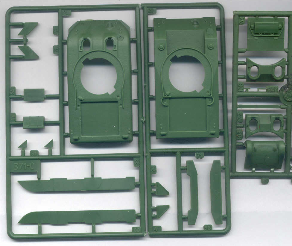
At far right is a section of the sprue E with the radial engine M4 engine deck (part 34). The air intake top is molded onto the hull so if possible scribe or saw cut a gap around the bottom. With addition of one part UM could have molded this cover separate, too bad UM did not. Below is the part with the initial direct-vision viewports and small driver and co-driver hatches (part 106). Below again is an optional driver area (part 172 with a rectangular cast hoods welded onto the glacis plate. One builder commented online that we have to use a strip of styrene filler under this part. At the very bottom is the one-piece cast, sharp transmission (a.k.a. differential) cover. (The one-piece transmission cover came in a rounded form and a more sharp, wedge shape form.) This transmission cover was more commonly seen on post 1943 Shermans I believe, so if we wish an early M4 we’ll need to scrounge up a 3-piece bolted transmission housing similar to that on the M3 Grant tank. In the above scan is at far left a sprue from UM kit no. 221 holding UM’s M4A1 small-hatch hull. Compare this with the ESCI-Italeri M4A1 big-hatch hull to see the difference. The hull looks reasonably accurate in shape. The driver hatches are molded open; the small holes atop the hull are for ventilation domes and fuel filler caps. We see there is no engine deck but a square hole; this is a common feature of the modular UM Sherman kits where UM provides an engine deck, rear plate and other small details depending on the variant.] From the welded hull M4 kit we have parts to make a direct vision or indirect vision M4, M4A2 or M4A3.] Below the smooth-edged cast M4A1 hull are the sponson bottom parts that close off the bottom of the hull above the tracks. In center is a sprue-C from kit no. 370 with the welded hull for the M4 tank. In addition to the choice of an optional engine deck the driver’s hatch area is also separate. The hull glacis and rear plates could use some weld seam detail. Below the M4 hull on the sprue are rear plates for the early M4 (left) or the later M4 (right).
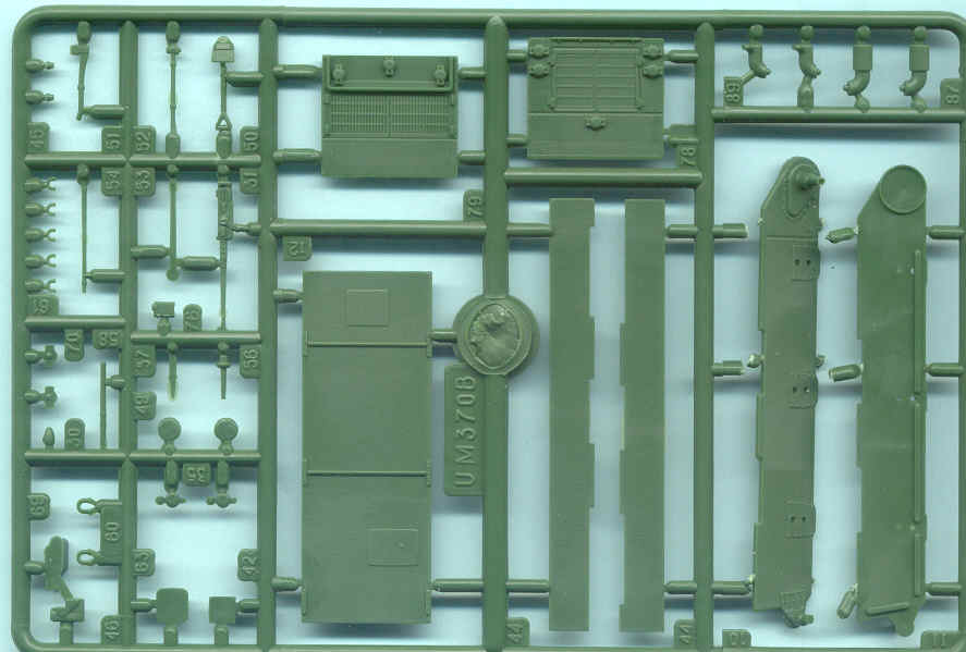
Sprue B here is common to all or many of the UM Sherman kits and includes the separate tools, lifting rings and headlights at far left. The tools are well done and I appreciate them being separate and not molded on. At top center are additional engine decks for an M4A3 and an M4A2. At upper right are what looks like M4A3 exhaust pipes and then what I think are very early M3 and M4 tank pepperpot exhaust pipes. I found no M4A2 diesel engine mufflers.
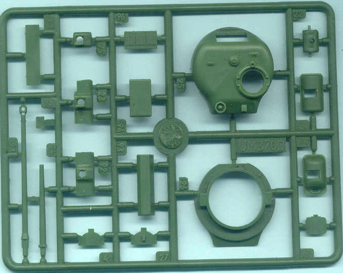
Sprue D above holds the early Sherman turret for the 75-mm gun. This sprue is common to both the M4 and M4A1 kit. I call it an early turret in that it has a low-bustle at the rear (where the radio is mounted), the split hatch commander cupola, and no loader’s hatch. The hatch rotates and in this case the hatch is rotated so the 50-calibre mounting post is oriented forward. At right is the gun mounts (parts 21 and 74) for the later M34 (part 75) and the M34A1 (part 23) rotor shields (gun mantlets) which are located on the right side of the sprue. The early mantlet for the M34 rotor shield is not as well detailed as that from Dragon. At the lower left is the 75-mm tank gun, and what is this, a 17 Pounder gun barrel? In addition to the Firefly gun barrel are a gun mantlet (part 92), and two storage boxes and the rear-turret radio box for a Firefly and common to British Shermans, a nice plus! The turret can use some cast texture but not too extreme in this scale. I have had success in replicating a cast texture by coating the plastic with liquid cement and stippling it with a stiff toothbrush. A product called Mr. Surfacer is popular with some modelers for creating cast metal textures. You can find out more about Mr. Surfacer at http://www.swannysmodels.com/Surfacer.html and http://militarymodels.co.nz/2010/05/06/working-with-mr-surfacer-part-1-creating-a-rough-cast-texture-effect/
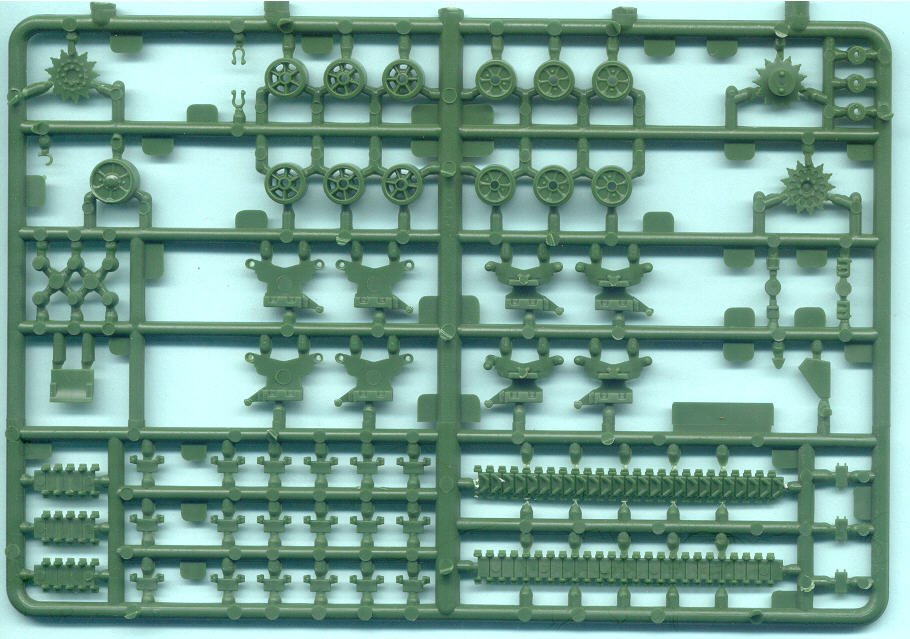
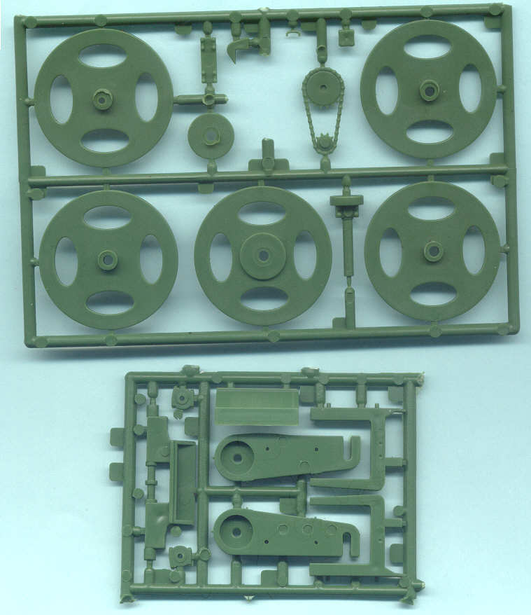
This is Sprue A of which there are two per kit. I think this sprue of track, and suspension bogies are common to all the UM Sherman kits with VVSS bogies. The bogie I have read described as an intermediate type and most common prior to mid-1944 with a strait arm holding the return roller. As Doug Chaltry reported in his UM kit preview the roadwheels are a little off-center, and they are not detailed on the back side, but there are two sets of them, plus extras. The six-spoke open wheels are also incorrect; they should have only five spokes not six. For more information on this see Doug Chaltry’s article at http://www.172shermans.com/VVSScompare.htm . We can perhaps replace these with extra open-spoke roadwheels contained in the Trumpeter M4 and M4A1 kits or Eduard M4. In UM’s recent releases such as the M10 Achilles Tank Destroyer kit I understand these roadwheels have been corrected to five spokes. There are four VVSS bogies per sprue making eight bogies in all for a tank having six bogies; why the extra two bogies? At the bottom are the link & length styrene track. See Doug’s review at http://www.172shermans.com/kitreviews/UM/M4_prev.htm for additional information. Be careful assembling the sprockets wheels. I assembled one set and though the mating pins lined up with the holes the sprocket teeth did not match. Both plain (part 37) and fancy (part 6) sprockets are included.
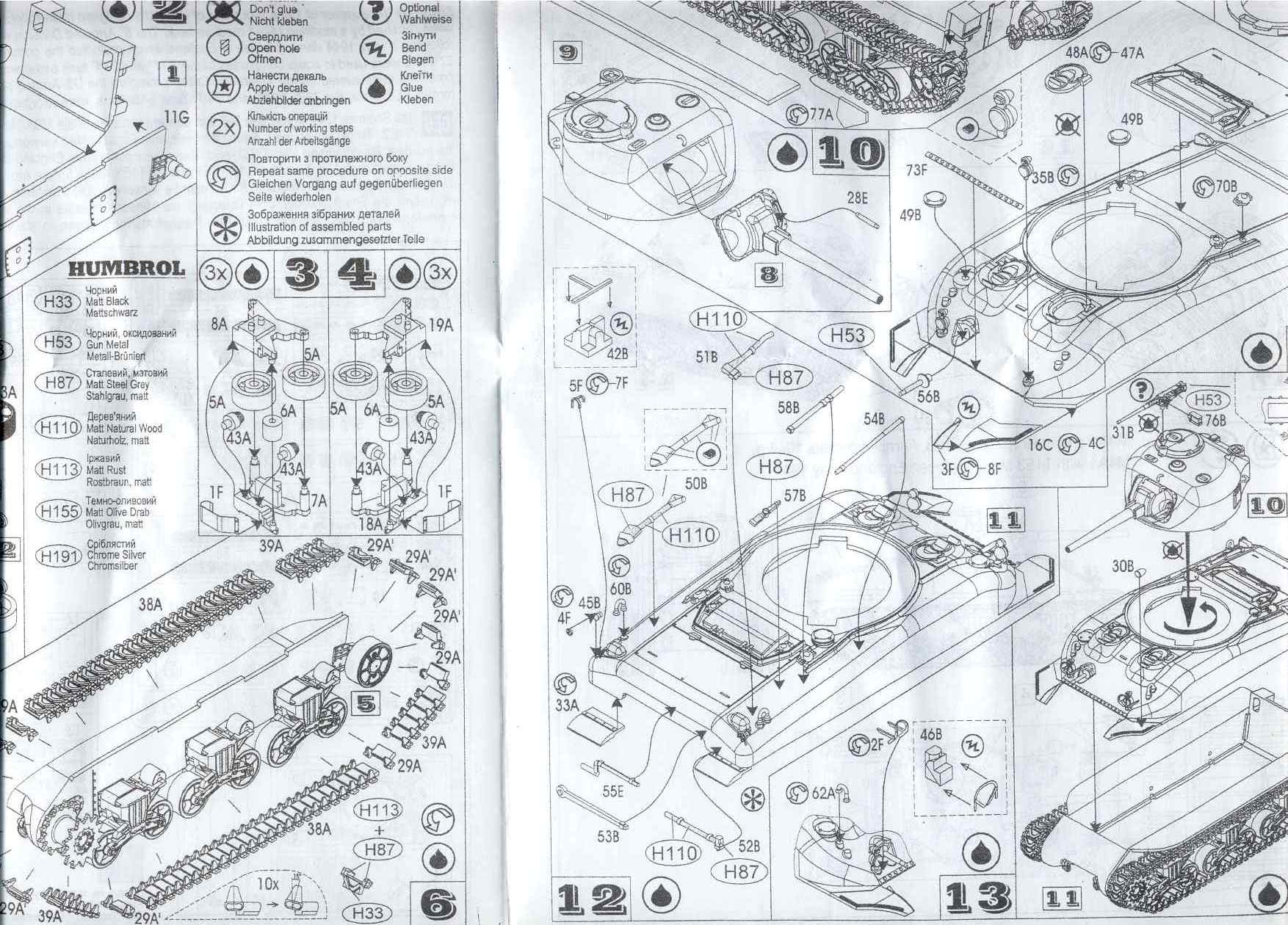
UM uses the common exploded-view type of assembly instructions with a good parts diagram, this is typical with UM’s other Sherman kits I have as well. The instructions look very busy and I think need to be studied well before you start gluing parts together. Photo etched brass part 73F I find interesting, this is the row of bolts attaching the transmission housing (part 14) to the upper hull (part 20). My opinion is that this is not a convincing way to go. All other small scale Sherman producers make this row of bolts integral in their plastic or resin transmission housing. One of the nicest things I like about UM is how they included three templates to help with folding the etched brass headlight guards and track skids. Why didn’t anyone else think of that? I suspect these templates will also work fine with Eduard and PART Sherman brass parts.
Sprues M and K in the M4A1 kit contain the parts for the T1E3 Aunt Jemima mine exploder. There are actually two of Sprue M at top included, the sprue containing the large rollers; one for each side of the tank. Looking at reference photos this roller assembly looks reasonably accurate though will need some small details like lift rings and bolts in various locations. The chain on the chain driver will be improved by drilling some holes between the chain links.
The last page of the assembly instructions for kit 221 has 5-steps for putting together the mine roller and appears clear. This vehicle just deserves to be set in a diorama with a couple of figures. One thing missing from UM’s kit is the rear pusher plate present on the Aunt Jemima M4A1 and other Shermans using this device. The pusher plate and frame was bolted to the rear so a second tank could help push the mine roller Sherman over rough ground. There are water slide decal markings for two vehicles on the sheet at lower right. The Aunt Jemima marking is colorful and really stands out but I hope it would not appear racially offensive or insulting in this day and age. A good reference for this mine roller is in Zaloga’s Modeling the US Army M4(75mm) Sherman Medium Tank book and his US Armored Funnies book, and the Tankograd Technical Manual (see references below).
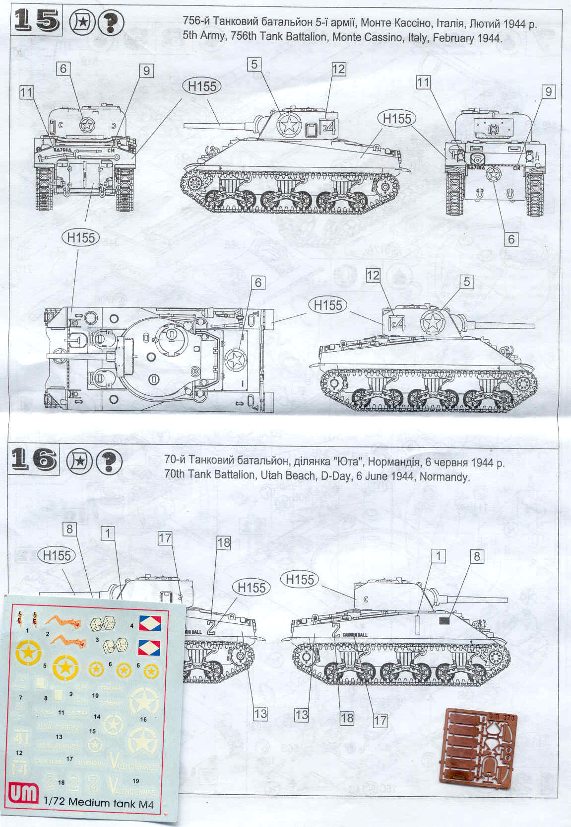
UM’s M4 kit has two diagrams to show the painting and markings for two Shermans. The water slide decal sheet at bottom left actually includes markings for four or five M4 tanks, including two US Army and one French Army tank. It appears to me that there are some inaccuracies with the decal markings. The turret number 14 marking with the white bar over it, for the 756th Tank Battalion model, is backwards for one side; one marking says 14 while the other is 41. Drawings portray, and the historical photos indicate that the number 2 for cannon ball was red outlined in white while UM portrays the 2 as just a white outline. At bottom right is the small etched brass fret which includes the six track skids for the bogies, headlight guards etc. I have found UM brass parts to be a little harder to work with than that from Eduard and Part but definitely better than not having it. Below I’ve included some wartime US Army photos, one photo of number 14, and two photos of Cannon Ball, so as to compare historical accuracy.
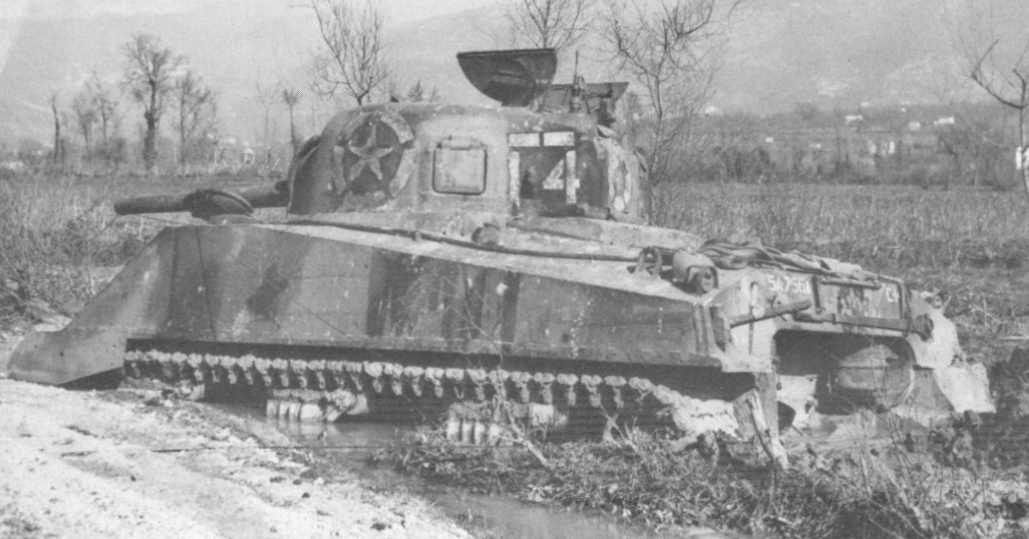
Here is a wartime photo of number 14 of the 756th Tank Battalion bogged down in a wetland in Italy. To assist in building the model of an accurate number 14 take note of the tool locations on the rear plate similar but not exactly as UM portrays them, the tow cable stowed on the port side, and part of the side skirt still attached at the front. There is an obvious two tone camouflage pattern with the star and white number 14 marking over the darker color, I am guessing brown or OD. UM does not portray this camouflage pattern. UM’s decal sheet portrays the stars as yellow color but in the photo they appear to me to be white like the numbers. There is no appliqué armor plate welded to the side indicating this is an early model dry-ammunition-stowage M4. The turret is a low bustle style as in the UM kit. From the edge of the mantlet that is visible it looks like the wider M34A1 type like portrayed on the UM model. There is a split commander’s hatch open and based on the time period I think there is no loader’s hatch. The open driver’s hatch is the small-hatch type but we cannot see what type of hood there is in front of the driver’s hatch. We cannot see what type of roadwheel or sprocket is used; the idler wheel looks like an open spoke type so I am guessing the roadwheels are also open spoke. The air cleaners are the round style and do not exactly match those in the UM model.
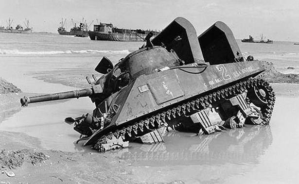
Here is a wartime photo of Cannon Ball of the US 70th tank Battalion stuck in a shell hole on a Normandy beach. I imagine that this M4 needed a full overhaul after being immersed in salt water. There are some big features here not included in the UM kit: the two deep-wading stacks on the engine deck, the appliqué armor plate on the port side, and up on the turret is a funny looking bracket for the Whiz Bang multiple rocket launcher. (According to Zaloga this Battalion was equipped with the rocket launchers but which were removed just before landing at Normandy.) Just behind the glacis plate we can make out a faint weld line. On the end of the gun muzzle is the remains of a waterproof cover. Above the mantlet is an adilade site used by the commander for rough aiming the main gun. The mantlet is the later M34A1 with the little armor wings on either side of the gun as supplied in the UM kit. Above the mantlet is one of the several gun mount lift rings that are not included in the model but can be fabricated with some copper wire. Above the tracks is the little strip of metal with holes where the sand skirt attached. We cannot see the roadwheels well but I think they are the stamped spoke style as supplied in the UM kit. On the bow in this and the photo below is a tall cylinder with a rod through it that I do not recognize. Hanging a little over the port side of the hull is a tow cable that looks to be attached to the bow.
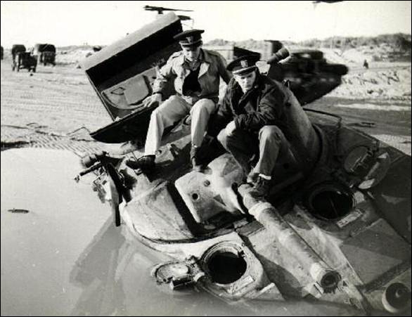
Here is another photo of Cannon Call with the tide being a little higher. (In the background is what I think is an amphibious DUCK truck.) The M4 driver’s hood visible appears to be the rounded cast style (matching that in the UM kit) with a good view of the appliqué armor plate welded to it. On the underside of the small hatch is the empty periscope bracket, a detail missing from the UM hatch. I find it interesting that there is no wire periscope cage over the hood or hatch periscopes. This is a good view of the interior detail of the commander’s hatch showing a grab handle and a pad, details missing from the UM commander’s hatch. To the left of the mantlet is a curved appliqué armor plate (not included in the UM kit but easily made with some styrene sheet). Just above the gun barrel we can make out two bolt heads in the mantlet. Conclusion Unlike another modeling company that claims to have the highest standards, UM has never claimed this and I will be honest, and I do not hold UM to the same standard. The UM kits are not up to par with the 1/72 Dragon, Revell and Trumpeter kits, and even the old ESCI/Italeri kit when it comes to detail and fit of parts. Still, I look forward to building a couple of these UM kits too confirm what other reviewers claim and as a challenge to my scratchbuilding skills. The Eduard or Part etched brass frets can help turn these into decent display models. As is the UM Shermans are good wargaming models. I appreciate the variety in Shermans that UM has released. When I started all we had in small scale was the ESCI, Matchbox and the Airfix Shermans, this is quite a nice change. References http://www.172shermans.com/kitreviews/UM/M4_prev.htm Doug Chaltry’s Modeling the Sherman Tank in 1/72nd Scale website. The M4 Sherman at War, The European Theatre 1942-1945, by Steven Zaloga. Concord Publications Co. (1994). A great and inexpensive book with loads of captioned photos and color plates. U. S. ARMOR Camouflage and Markings World War III, by Bill Mesko, Squadron / Signal Publications (2005) US Armored Funnies, US Specialized Armored Vehicles in the ETO in World War II, by Steven J Zaloga, Concord Publications Company (2005). Modeling the US Army M4(75mm) Sherman Medium Tank, by Steven J Zaloga, Osprey Modeling, Osprey Publishing (2006). http://the.shadock.free.fr/sherman_minutia/index.html Sherman Minutia website, a great online reference. Tankograd - Technical Manual Series – M4 / M4A1 Sherman, Number 6001, Tankograd Publishing. Contains detail photos of the T1E3 mine roller. |
| Modeling the Sherman Tank in 1/72nd Scale |