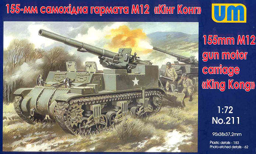
| 155mm M12 GMC | UM Kit #211 |
| Article by Stephen Brezinski; last updated 3 March 2016 | |
 |
|
| Modeling the Sherman Tank in 1/72nd Scale |
| 155mm M12 GMC | UM Kit #211 |
| Article by Stephen Brezinski; last updated 3 March 2016 | |
|
|
| This review covers the
US Army M12 Gun Motor carriers (GMC) kit from Uni Model
of Ukraine. Along with the UM M12 kit, UM has a new
kit of the M30 ammunition carrier that accompanied and
supported the M12. So much more can be discovered
about a model kit from assembling it of course. For
a look at the kits in the boxes please see this article. For me, the process of building a
model kit is as important as the outcome. I love
seeing how a manufacturer has engineered the kit, how it
assembles, and how I can make it better.
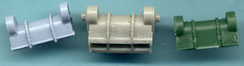
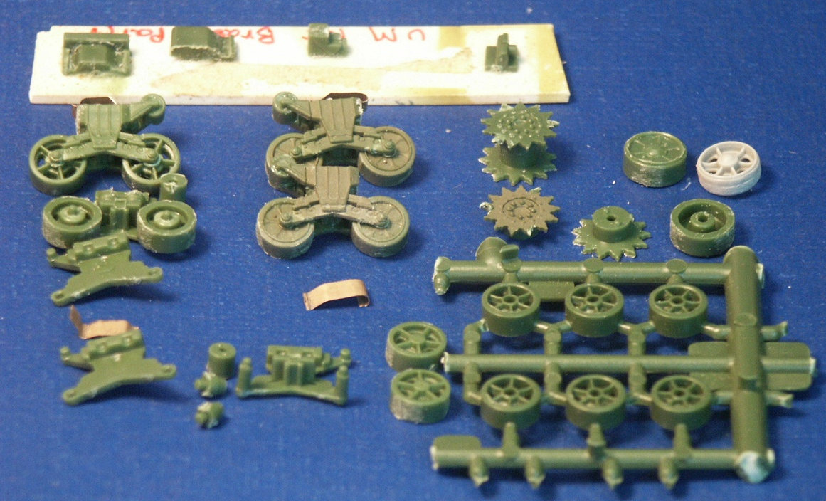
In the in-box preview of these kits the final drive (differential covers) were discussed and the construction problems with the 5-part UM final drive assembly. A lot of scraping and sanding was needed to assemble the UM assembly at far right; not a fun project to do more than once; actually not a fun project to do once. I first noted this problem in fit during my assembly of the UM M4A4 model. I was initially perplexed and thought I must be doing something wrong: No kit maker could make a part so hard to assemble!? I had heard from no other modelers complaining about building this UM Sherman final drive assembly and that maybe only I was doing something wrong. Fortunately for me I finally heard from another modeler who had the same problem. For this project, the UM kit assembly was used for this M12 model kit, but for the UM M30 model a spare gray resin final drive assembly from Wee Vehicles (gray resin part in the center) will be fit in. At far left in the photo above is a spare final drive assembly from a Heller M4 kit.
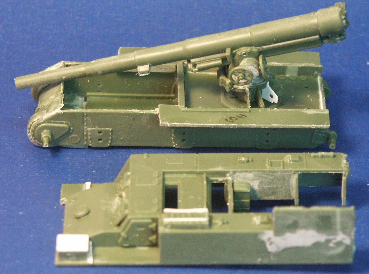
The UM lower hull for their M12 and M30 assembles similar to their M4 Sherman model kits. Notice that at the very rear of the gun compartment floor (part-10C) I had to fit in a fillet of white plastic to fill in a gap. The UM upper superstructure has fewer parts than the ESCI M12 model but has considerably more parts for the interior and for the tools and gun. Notice the gray model putty to blend in the seam for the parts 33C and 12H. Notice that the gun has a white scratchbuilt replacement brace for a gun pedestal part (part-29H) that I lost. In the forward area of the gun compartment we can see one of the square air cleaners for the engine. The kit comes with round, cylindrical air cleaners, I think it was a nice attention to detail to not just give the two kits the same air cleaners. The M30 and M12 were based on essentially the same hull, but in historical photos I have seen many little variations such in the wheels and fittings.
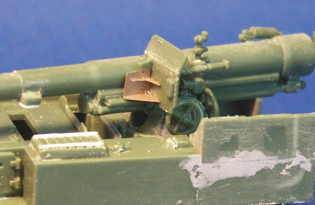
The gun shield (parts-24C) for the M1917 gun appears much more accurate than the ESCI part-16 and is enhanced by nice etched brass parts. The grouser box (Parts-3H) has been given two strips of styrene to simulate the braces to hold the grousers in. The model features a well rendered gun sight that is not supplied in the ESCI M12 model. The details on the 155-mm gun compare well to my reference photos so I used it to help correct the details of the ESCI gun. An easier way to get a better gun for a great display model is to use the M1917 155-mm gun from the one of the RPM GPF gun kits (see review at http://www.onthewaymodels.com/reviews/RPM/AMagnus_RPM_72602_review.htm).
The rear spade for the M12 is assembled except for the etched brass tread plates. Notice the scratchbuilt brace on the forward mudguard (fenders). With the upper hull largely molded as one piece the UM kit is missing the line of rivets along the upper edge that is present on the ESCI M12 model. Looking where the upper hull meets the final drive assembly I am unhappy about the fit; despite sanding and some trimming the upper hull sits too high, or the final drive assembly sits too low.
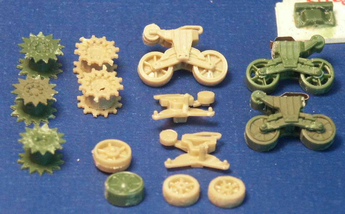
A comparison of the UM wheels with the ESCI wheels shows the greater number of parts used in the UM suspension and the overall better rendered detail of the UM parts. To be frank, the UM suspension though better than the ESCI parts are still not as well done as the Dragon and Heller Sherman VVSS bogies and wheels. These are the same suspension parts as included in the UM and the ESCI M4 Sherman Medium Tank kits.
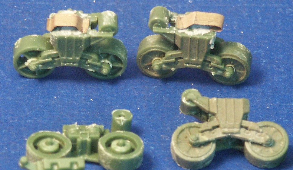
Above and below are photos of the VVSS bogie assemblies used for my M12 and M30 models. To add some variation the two vehicles were given different wheels.
Closer views of the UM bogies in various stages of assembly and different roadwheels, and variations in the track skid.
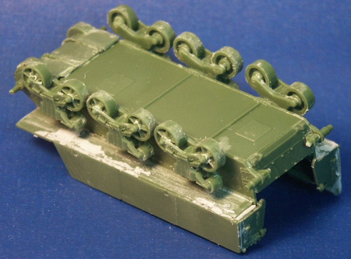
The underside of the hull is the same as in UM's M4 Sherman model kits. Without having seen the underside of an M12 GMC, I surmise that this part is incorrect as I suspect the engine plates should be in the hull center since this is a mid-engine vehicle.
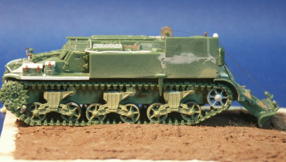
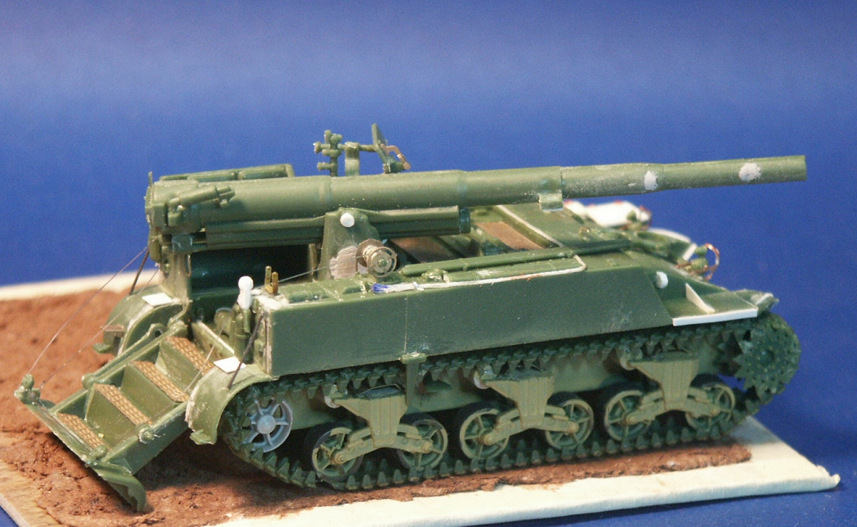
Compared to the UM M30 kit built in conjunction with this M12 model, with the M12 I opted for an early variant with the open spoke roadwheels and idler wheels and early style track skids. The front mudguards have been given a scratchbuilt brace on both sides, the storage boxes have been given new lids, and the grouser box has been given two braces on top. The light gray model putty filler is obvious in the part seams needing filling.
At this point we have skipped ahead: What is new is the strip of plastic at the front, simulating the strip of sheet metal for hanging the side sand skirts, like those seen on the Sherman tank. The strips had a horizontal line of bolt holes. In historical photos I have never seen the side skirts actually fitted to an M12 or M30. A Heller kit open spoke idler wheel (the pale gray wheel at the rear) has substituted the UM idler wheel (part-3A). On top of the superstructure is a tow cable made from string and mounted to the deck. Neither the M12 nor M30 include the towing cable. Cable has been simulated for the rear spade's cable & winch lifting system, using fine monofilament fishing line. UM is commended for supplying four small pulleys (parts-11C) for the cable that are attached to the rear superstructure and the spade. Based on photos of the real M12, I noted the pulley immediately behind the cable drum was actually two pulleys and the cable went between the two pulleys. Immediately in front of the last VVSS bogie we see a sword-like bar (part-7H) hanging down from the upper hull; there is one of these on each side of the upper hull. Parts 7H should be placed immediately in front of the last VVSS bogie. Not included is a brace that goes from part-7H to the front of VVSS bogie.
This shows a better view of the winch and pulley system for lifting and lowering the spade (assembly Step 13) in the back. There are etched brass tread plates (parts-2F) on the steps of the spade; a nice touch. Left of center on the starboard side of the superstructure rear we can see the double pulley made from white styrene bits and which replaces part-11C). Yes, there are still two track links missing from under the last roadwheel on the starboard side, these will come soon. The vehicle is mounted on a base with simulated earth and will be portrayed next to the UM M30 model. The earth is made from CelluClay instant paper mache tinted with brown acrylic paint. The nice simulated wood-pattern edges of the base material are protected from the paint with painter's tape.
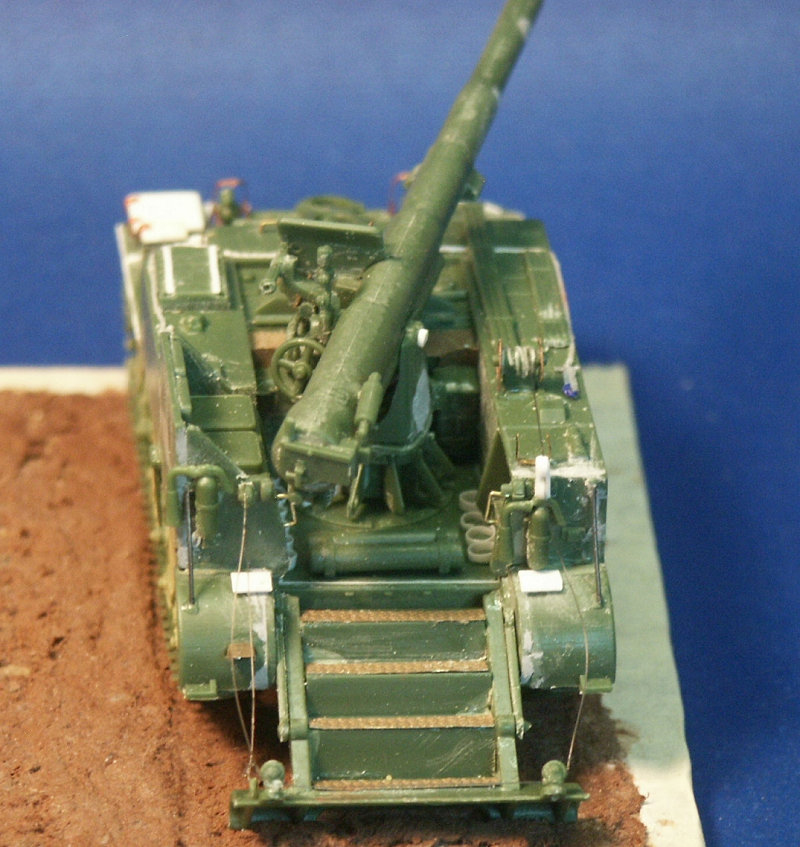
View of the front, the bow Mr. Surfacer 1000.has been painted over the differential cover to simulate a cast texture, even though in reality we would not be able to discern a Sherman's cast metal texture in this scale without a strong magnifying glass. At the upper edge of the 3-piece differential cover is UM's row of bolts simulating the bolts holding the differential cover to the glacis plate of the Sherman. This is a feature on all of the ten or so UM Sherman kits I have. Note the grab handles on the hatches fashioned from brass wire. On the gunner shield on the port (left) side of the gun are some etched brass parts. On each side of the upper hull sides a tad below the driver's visors are the homemade lifting rings missing from the UM and the ESCI M12 kits. Not very visible are UM's etched brass headlight guards (parts 19F). These brass guards are a nice idea but they bend out of shape so easily it is difficult to not deform them. I found the Eduard and the Dragon etched brass headlight guard parts to be more substantial in that they are a little stiffer and hold their shape better.
A view of the rear displays the little added details like the rings to support the upright artillery rounds on the floor. The cables for the spade hang loose but should be tighter when the kit is glued down. The monofilament line can be tightened by carefully heating the line with some gentle heat such as a hairdryer; but be very careful to not overheat and deform other parts. Perhaps insulate surrounding plastic parts with tissue. In historical photos there is some slack in the cables, as long as the cables hang down, the way gravity does with things.
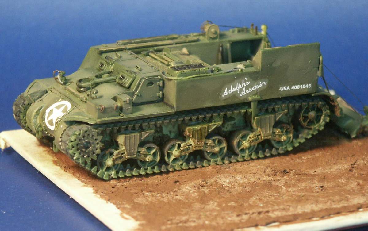
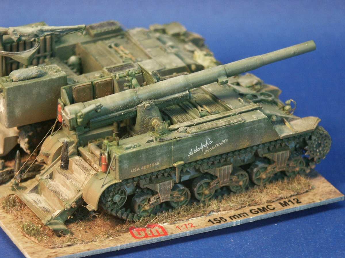
Skipping ahead several steps, several coat of paint and a dark wash have been applies then clear acrylic gloss over the decal areas. These markings are for the US Army 991 Field artillery Battalion serving in Germany during autumn of 1944 (see https://army.togetherweserved.com/army/servlet/tws.webapp.WebApp?cmd=PublicUnitProfile&type=Unit&ID=10155). I should have chosen markings for the same unit as the UM M30 model to be mounted next to this model. I chose the markings based on what I thought looked appealing to me but should have considered consistency of the vehicles serving together and mounted on the same model base. I found the kit decal markings are a little stiffer than decals from other manufacturers such as Revell and Trumpeter. One marking broke when trying to remove it from the paper sheet. Notice how the decals have a flat finish and the decal film certainly stands out from the gloss finish applied underneath the decal. Because the decals were extra stiff I found the required an extra strong (hotter) decal setting solution. The star decal on the nose was a little too large based on the historical photos and curved up over the flanges and bolts of the 3-piece bolted differential housing making the setting solution absolutely needed.
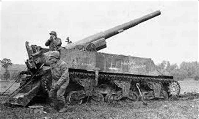
Here is a historical photo of Adolph's Assassin during WW2. Examining closely I notice that I applied the starboard side vehicle name "Adolph's Assassin" too far back on my model. It is hard to see well because the roadwheels are caked in mud, but I believe them to be the open spoke wheels.
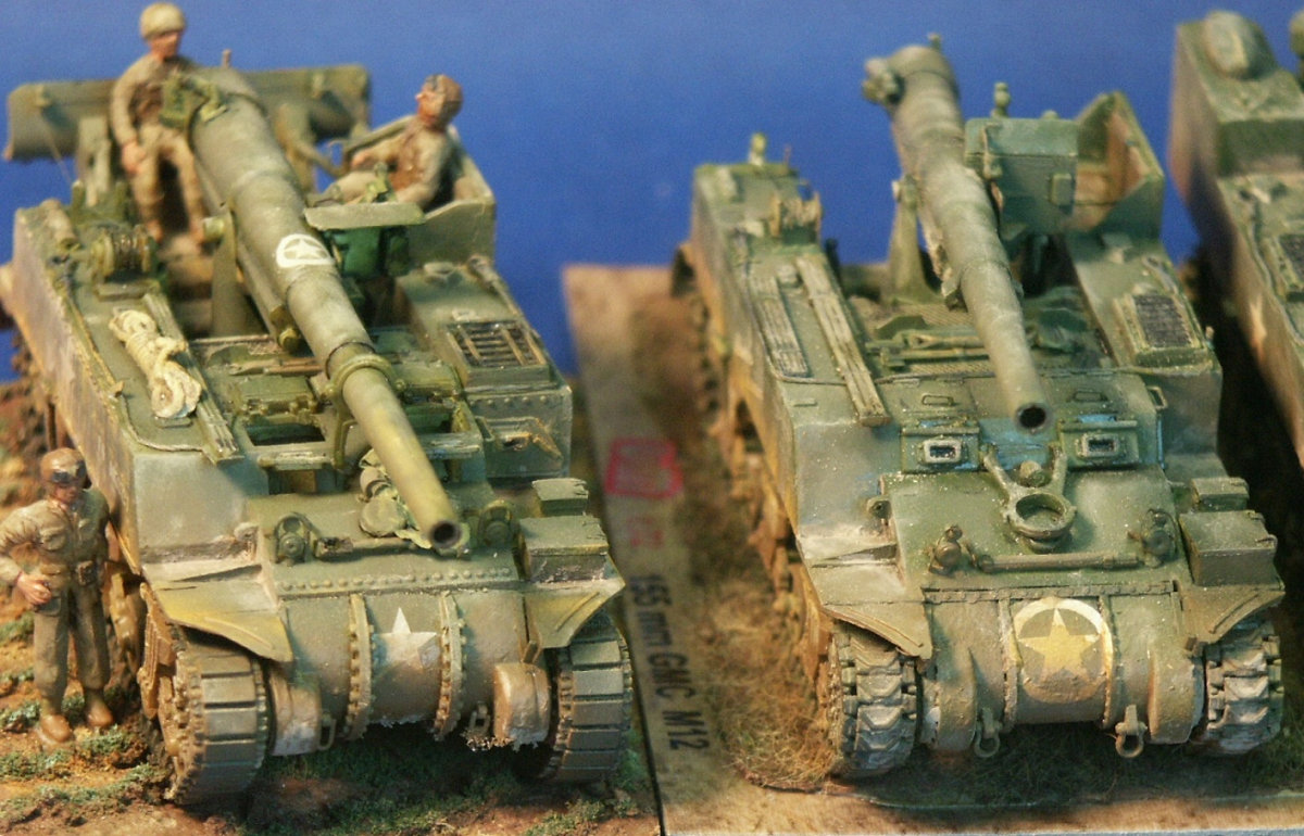
The M12 model next to the completed UM M30 ammunition carrier model. The base is a piece of wood pattern floor tile with Celluclay simulated earth and static grass.
The UM M12 and M30. Some good figures would be real nice to dress up this display.
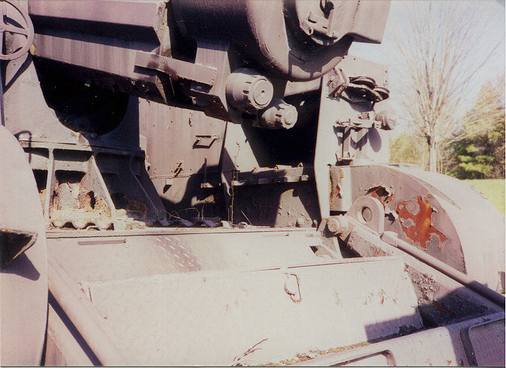
The UM M12 kit at far right side by side with the ESCI M12 GMC kit at left. Even though the ESCI 3-piece differential cover is not perfect, I still prefer it over the UM bolted differential cover in appearance and especially in ease of assembly. The fact that ESCI supplies three crew figures with their M12 kit is no advantage considering that the ESCI kit figures are of mediocre quality at best, in my humble opinion. The ESCI kit has been given extra flat block track from a Heller kit, this track is what I have most always seen on the M12 and M30 in historical photos. References U.S. Self-Propelled Guns in action, Armor Number 38, by Jim Mesko, Squadron/Signal Publications (1999) The Sherman Design & Development, Son of Sherman, Volume 1, softcover or hardcover book by The Ampersand Group Inc. (2013) Sherman Minutia website http://the.shadock.free.fr/sherman_minutia/index.html Tankograd Technical manual series 6030 about M12 and M40. U.S. WW II Heavy Self-Propelled Artillery M12, M40, M43, by Verlag Jochen Vollert, Tankograd Publishing (2014) Paperback. Below are photos I took of an M12 that was on display at Aberdeen Proving Grounds in Maryland, USA; perhaps the only surviving M12 GMC.
Above is a photo of the rear showing the gun base, the recoil spade & steps, and the rear of the recoil cylinders under the gun breach. On the right, starboard, side of the hull rear we see the two pulleys for the cable for lifting the recoil spade. This bracket with two pulleys that in use would be vertical rather than laying on its side like this. The cable would run from the winch up forward through the pulley and to the spade.
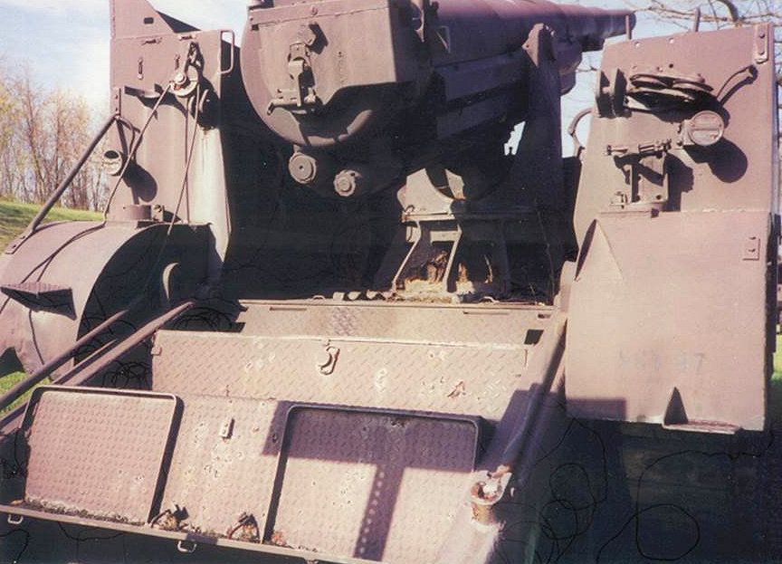
On the left side we have another pulley that still has some cable strung through it. Also on the left side we can see the brace going down to the mudguard. In historical photos I've noted that these braces could be made from thin rod such as here, or made from flat bar. Here we can also see the two tail lights, and the two fire extinguisher brackets. At lower right we can see a couple of the flat bock tracks.
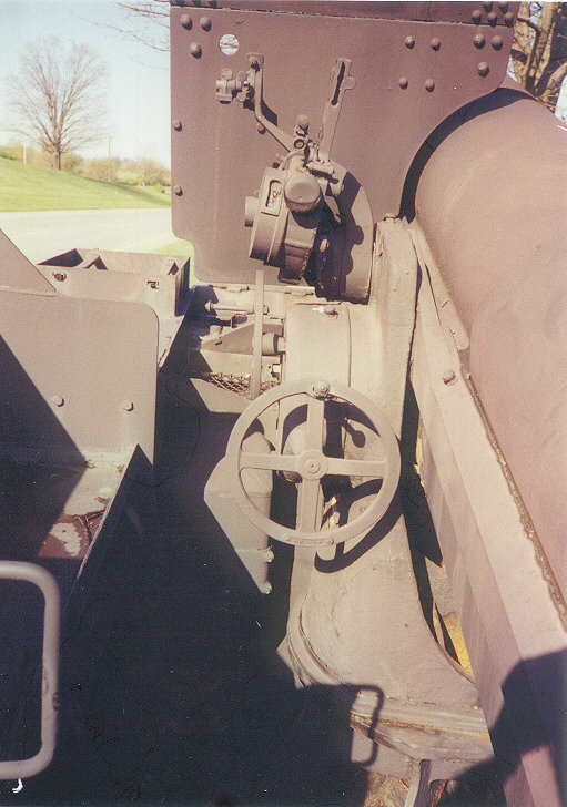
The port side of the 155-mm gun and the gunner's station. The traverse hand wheel is visible but the elevation hand wheel, as well as the gun sight are missing |
| Modeling the Sherman Tank in 1/72nd Scale |