| M12 GMC | ESCI Kit #8362 |
| Article by Stephen Brezinski; last updated 19 December 2015 | |
 |
|
| Modeling the Sherman Tank in 1/72nd Scale |
| M12 GMC | ESCI Kit #8362 |
| Article by Stephen Brezinski; last updated 19 December 2015 | |
|
|
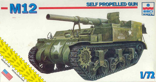
| This review covers the
1/72-scale US Army M12 Gun Motor Carriage (GMC) from the
old venerable ESCI company. Along with the UM M12
kit, UM has a new kit of the M30 ammunition carrier that
accompanied and sported the M12. I considered doing
a comparative construction review of the UM 12 and M30
along with this ESCI model but decided it would be too
long and complicated. So much more can be discovered about a model kit from assembling it of course. For a look at these kits in the boxes please see this article. For me, the process of building a model kit is as important as the outcome. I love seeing how a manufacturer has engineered the kit, how it assembles, and how I can make it better. This is my rendition of building this ESCI kit. I don't claim to build the best models, or that this is the only way to assemble and detail this model. Since the box art was covered in the In the Box Preview I won't it again in detail. The painting looks like reasonable representations of the actual M12 so should be able to help with assembly and painting. Spoiler Alert: after assembling I found the box art to be a more accurate representation of the M12 than the enclosed model kit.
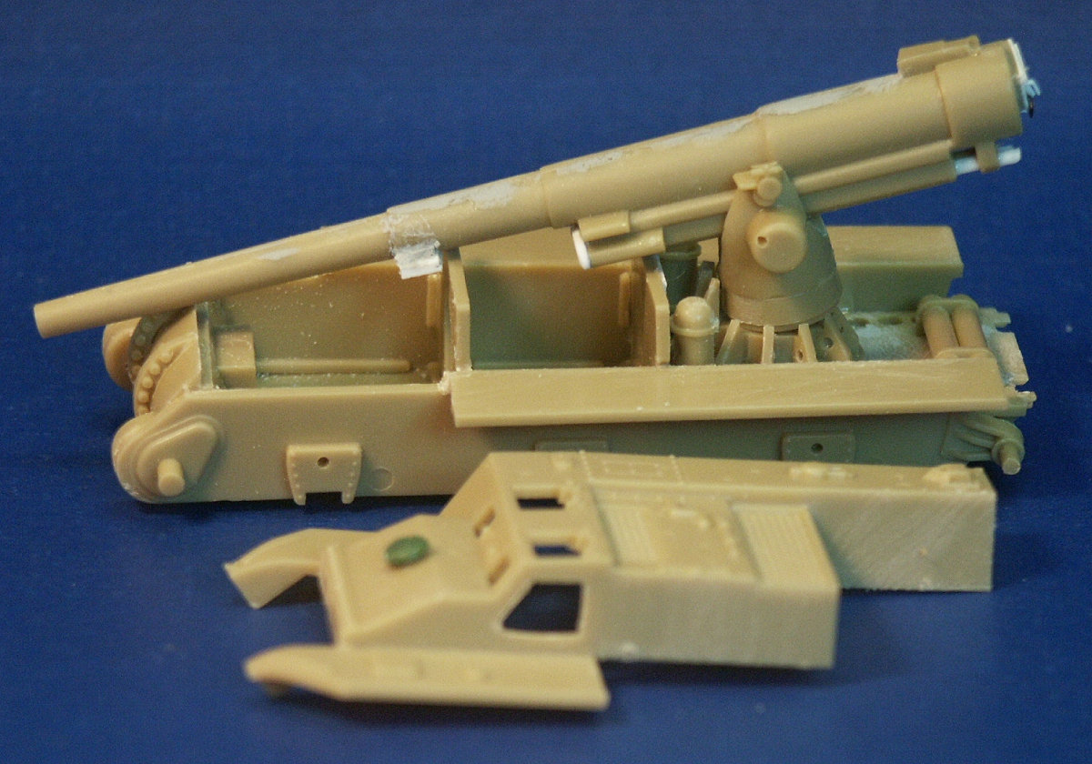
The lower hull assembles much like the ESCI M4A1 Sherman kit. Significant differences are the 3-piece cast differential housing that the M12 kit comes with and the revised rear area. In the foreground is the upper hull section with the driver's side door cut open. On the partially assembled 155-mm M1917 or m1918 gun we have changes and corrections made from white styrene. The top hatches for the upper hull superstructure are already open and with separate hatches (arts 34 & 35). There is a separate hatch for the driver's side door (part 101) but to portray the door open we need to cut the doorway out. On the bow is a replacement ventilation dome taken from UM spare parts; this ESCI feature is molded on and too low to undercut.
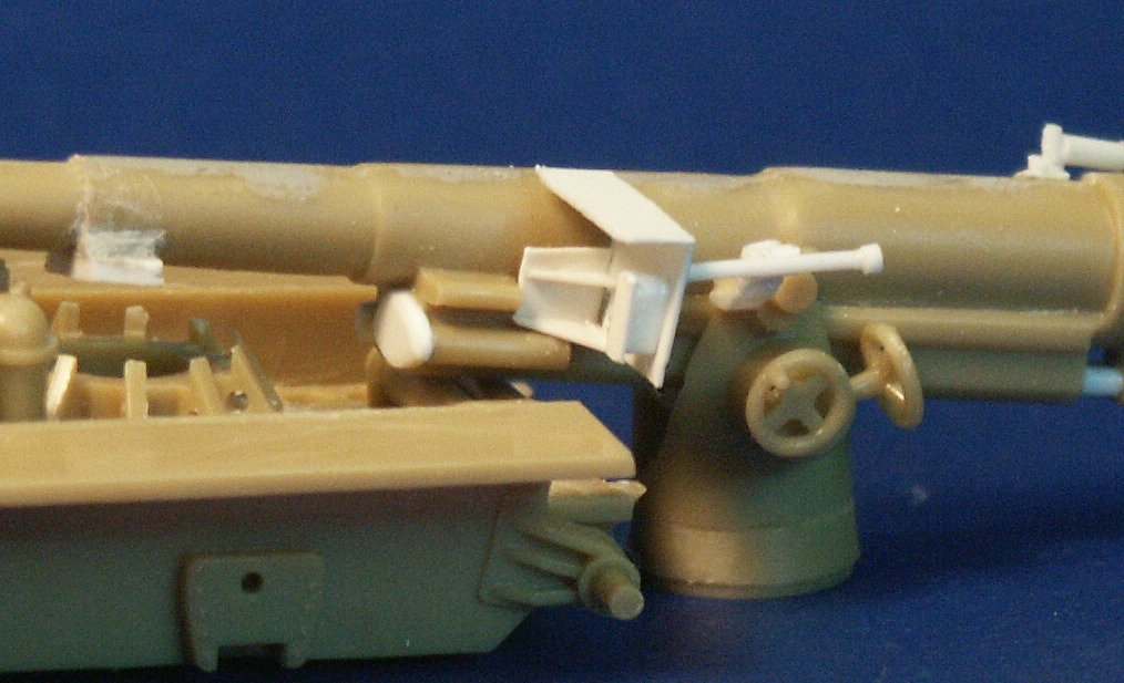
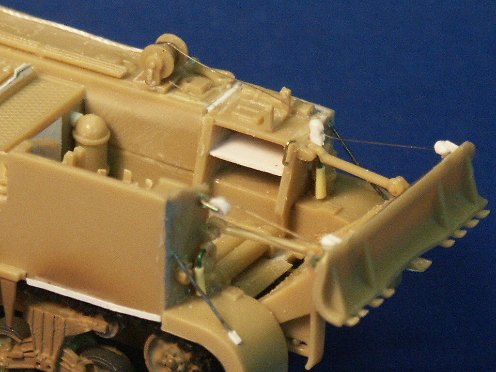
The kit comes with a rather crude shield for the gunner so I replicated in thinner styrene sheet using the UM parts and my photo references. The gun's elevation and traverse handwheels (parts 21 & 22) are a wee bit smaller than those in the UM kit. The supports on the gun pedestal are much too thick, UM made their pedestal braces as separate pieces which are more to scale. The M12 used three variants of this gun, the M1917, M1917A1 or M1918, so I expect there could be some variations between a surviving M12 GMC, historical photos and our model kits.
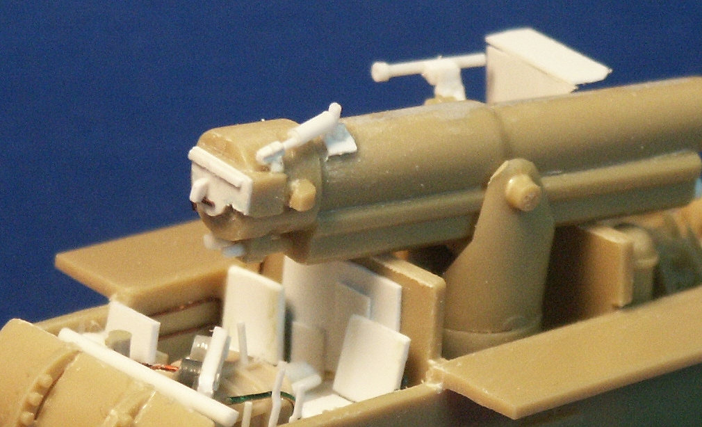
The breech area showing the scratchbuilt improvements and driver's area. My goal was not to produce a microscopic detailed model; with all the models I want to build I do not have the time or desire to take months to detail one model. I was unsuccessful finding interior shots of the M12 so ad-libbed using the M4 Sherman interior and a M12 interior built be another modeler as references.
Assembly of the upper hull in sections. The UM M12 kit assembles differently but is just as complicated. Be careful and dry fit before gluing. On the table in the foreground are the portside upper hull parts and 17 & 27. At far right are subassemblies of the rear seats and storage shelves (parts 32, 33, 40 & 41). Note the locator holes for the VVSS bogies which make it easy to locate and securely glue the VVSS suspension.
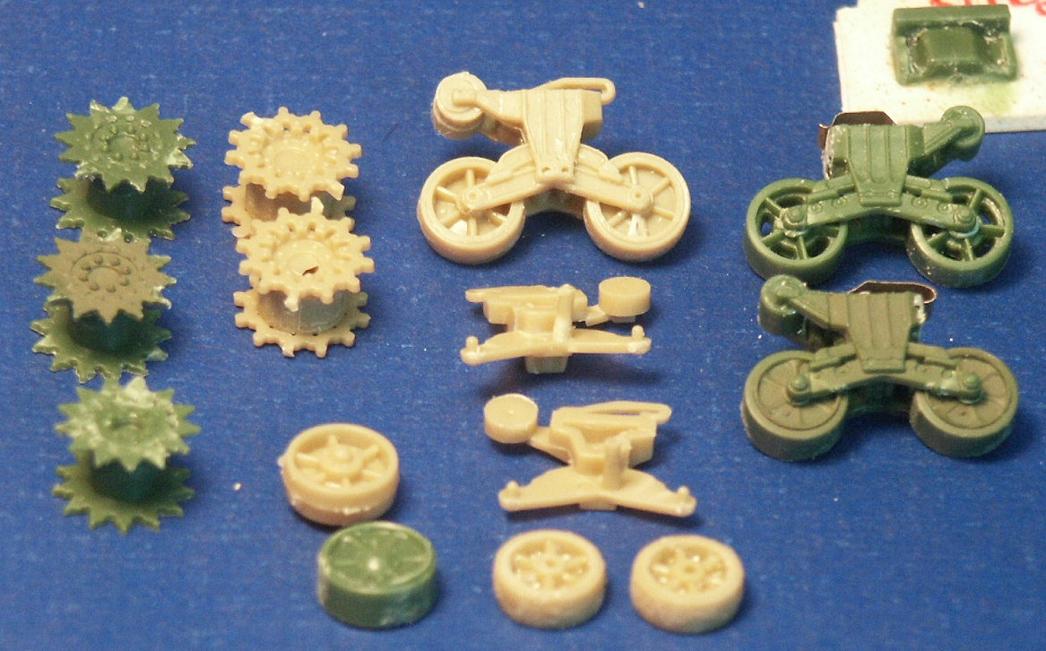
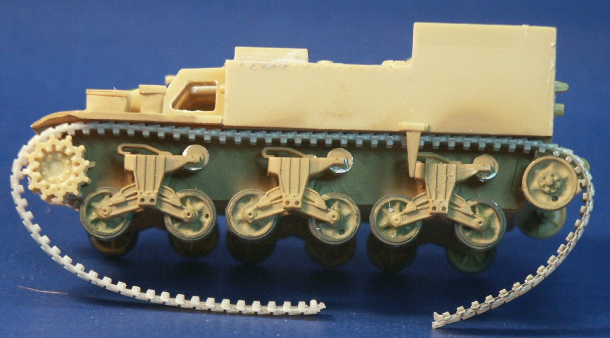
A comparison of the green styrene UM suspension parts and the pale tan styrene ESCI parts. The ESCI VVSS suspension is the same as in the small scale ESCI (Italeri) M4A1 and M4A3 models. The ESCI sprocket wheels are a bit crude, inaccurate; for example the sprocket is missing a tooth. The ESCI roadwheels appear to represent the six spoke stamped roadwheel but the spokes are much too prominent. (I was going to mention the roadwheel part numbers but oddly each roadwheel has a separate part number) The UM stamped spoke wheels at right are not perfect but are more accurate than the ESCI. For this model I have tried filling in the deep recesses between the spokes with Micro Krystal Klear, a kind of a white glue good for making clear lenses, though Elmer's white glue would also work. Use multiple layers and let them dry in between layers till the glue almost, but not quite, covers the spokes.
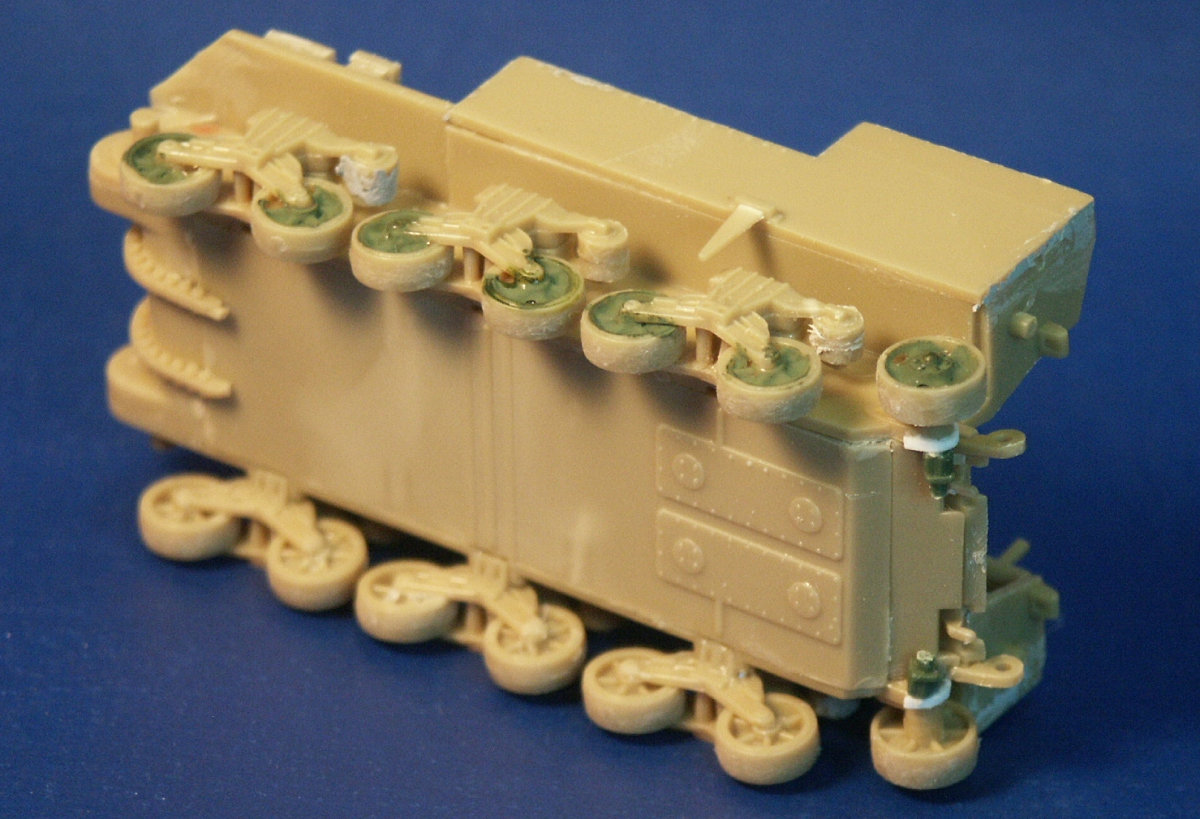
The underside showing some lower hull details. Since I have no photos of the underside of the M12 I cannot state if this is accurate or not. One thing I can surmise is that since the radial engine of the M12 was centrally located, in front of the gun mount, so the engine access hatches on the underside should maybe not be in the rear of the bottom hull plate. On the rear note the improvements to the idler adjustment mechanism with some styrene pieces and parts A32 & A40 from a UM Sherman kit. The recesses between the spokes of the roadwheels have been filled with glue and test painted to check for air bubbles. When building the model I was torn between what needed replacement, what could be fixed, with still using as many of the kit parts as possible. If I were building a contest model I would have replaced the wheels with better ones.
I am puzzled by the long triangular spike-like thing hanging down next to the rear VVSS bogie. It is present on historical photos of the M12 and also on the UM M12 kit. On the port side storage area I replaced a shelf under the seats (part-41) with a thin sheet styrene, on the front of the compartment I added a missing access plate. Interesting features are the cylindrical air cleaner up against the centrally located engine compartment. On the very rear of the gun compartment floor are two long tubes that I presume to hold propellant. The UM M12 also features these tubes but I have not seen them on the floor of a real M12 in historical photos, just some brackets presumably to hold these tubes. On the floor also note the large holes which hold the kit's 10 separate 155-mm projectiles (parts 3 - 12). I have a hard time thinking that the M12 would travel with these rounds just sitting upright on the floor with no apparent brackets to hold them secure. The UM M12 kit places loose 155-mm projectiles in the same location.
This is why I hate the stiff, mediocre detailed, polyethylene band track that comes with many ESCI kits. Did I mention that this stuff is also resistant to just about all common glues? The ESCI track appears to represent what I think is T49 rubber block track; the most common track type I have seen on the M12 is the T51 with flat blocks. I honestly wanted to give these ESCI track a chance but could not just put all this effort into detailing and then have the chance it would look like a toy by using the ESCI track. Note the air bubbles in the Micro Krystal Klear of the idler wheel and several of the roadwheels. Did I mention that the sprocket wheel is missing a gear tooth so replacement tracks should be a little stretchy to fit onto the sprocket; or you could just replace these mediocre sprockets with more accurate ones. I recommend leaving off a lot of the small parts and the mudguards till the track is mounted and maybe even till the model is secured to a base so fumbling hands do not accidently break off parts.
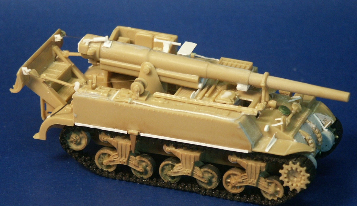
Skipping ahead a bunch of steps we have all the changes and scratchbuilt detailing. The ESCI tracks have been replaced by extras from a Heller Sherman. Braces have been made from thin sheet styrene for the fenders. A strip for attaching sand skirts are affixed to the side of the upper superstructure. The headlight guards have had a brace added to make them more accurate; though the headlights (parts 112 & 113) are still not as good as the UM parts with an etched brass headlight guard. In many of the M12 photos I noted a welded-on lifting ring on the side of the glacis plate, this lifting ring is not visible on the ESCI box art nor included in the kit, it is visible on the UM M30 box art. The lifting rings are easy to make: drill a hole in a piece of thick sheet styrene, cut it to shape, and glue it into place. The tow cable (kit part-58) ends were snipped off and attached to a length of string which is a more in-scale and realistic cable. Neither the UM M30 kit nor the UM M12 kit include or mention the the tow cable.
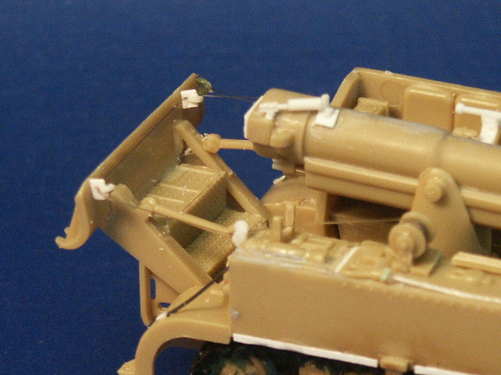
The rear spade helped absorb recoil of the gun as well as being steps for the crew. The spade was lowered and raised by pulleys and cables back to a winch on the M12's starboard side. While the UM M12 kit gives us some parts for all the little pulleys, the ESCI kit gives us nothing but the winch. The cable was reproduced with monofilament fishing line. Once raised the spade is secured in place by bracket arms (parts 105 & 106) and the cables could be slack.
A view of the rear port side and details of the rudimentary pulleys, the cylindrical air cleaner. If you look the at the port upper superstructure rear I added the hose and horn for the fire extinguisher. ESCI just supplies the extinguisher cylinder while UM supplies two entire extinguishers in their M30 and M12 kits. The fender braces for both the ESCI kit and the UM M12 kit are too thick so they were replaced by copper wire.
After scrutinizing a photo I noticed that around the base of all those artillery projectiles (parts 3 thru 12) standing upright on the floor there are low rings along each side of the gun compartment deck. These rings were simulated by cutting low rings off a plastic bar straw and gluing it to the floor with Super (cyanocrylate) Glue. Straps made from tape have been added to the hand tools to represent the leather straps.
At this point it is time to mount the model on a base for easier handling. While studying and building this model I kept on wondering where the engine exhausted to. Eventually I found buried in Step-6 of the UM M30 instructions the location of a flange and flared exhaust pipe protruding from the side of the lower hull between the 2nd and 3rd suspension bogies. I then found the exhausts on a WW2 period photo. ESCI offers no parts for the exhaust pipes, so using the UM kit parts as a guide I have replicated the exhausts on the ESCI model with some white sheet and tube styrene. Exhaust pipes are installed on both sides of the M12 and M30.
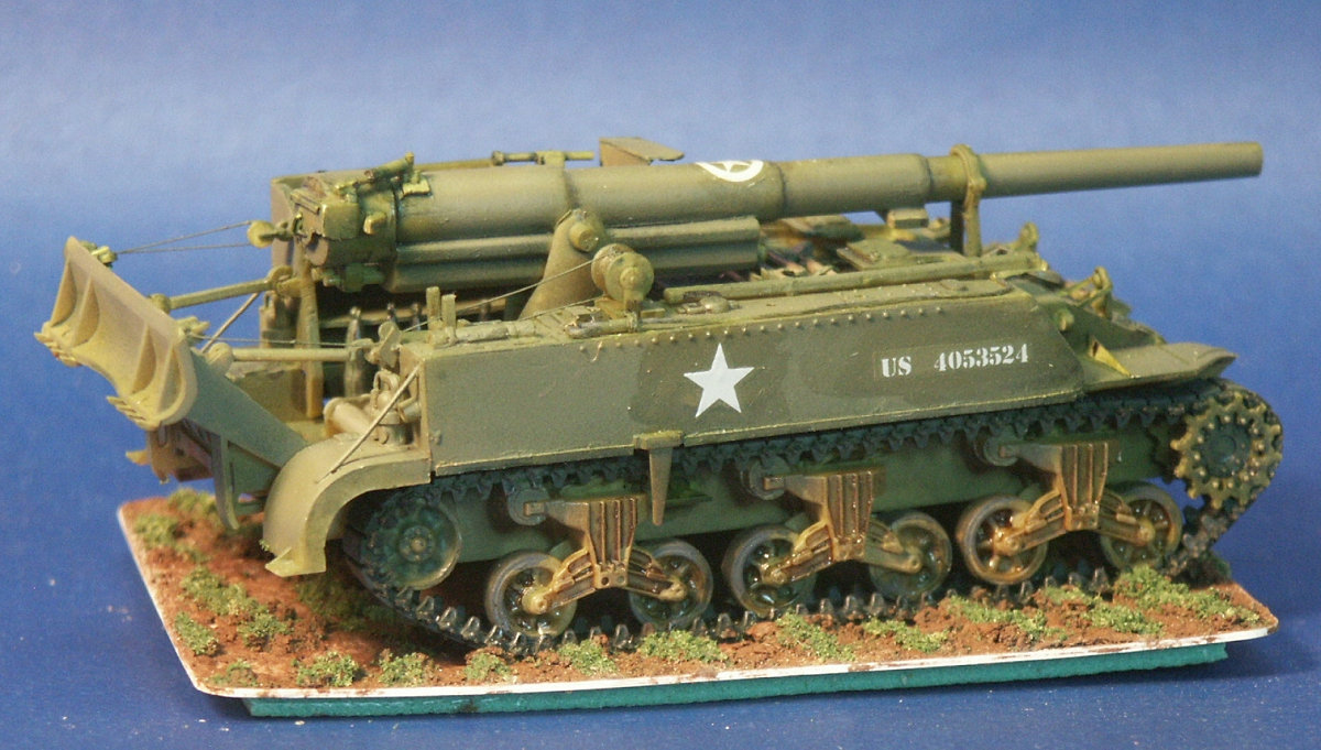
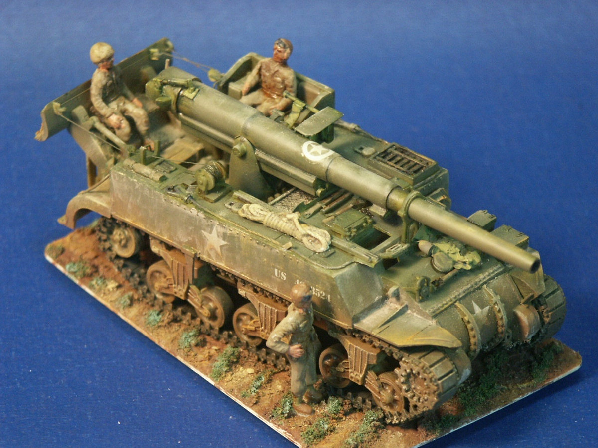
Skipping ahead. The M12 was given a coat of olive green acrylic, then a dark wash into the recesses, and finally a lighter olive drab. Clear acrylic gloss was applied over the locations for the decal markings. Notice that the decals film is curling. I am hoping the will eventually flatten out. This curling may be the result of the decal setting solution I used, a stronger solution than the solution I typically use.
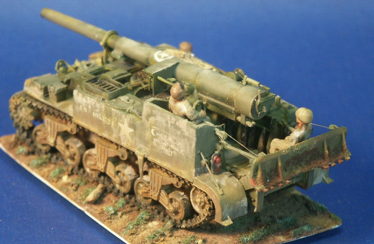
Weathering is still to be done. The M12 has been glued to a base covered with Celluclay Instant Paper Mache tinted with brown paint. The base is an old plastic identification or library card. Celluclay is a dry material that appears to be made of fine shredded paper and a binder. Instructions say to mix with water but I add acrylic paint for coloring and white (Elmer's) glue to help with binding, and perhaps fine sand for texture. Be careful in that a thick layer of Celluclay shrinks when it dries and can cause a flexible base curl up at the edges, as it is doing here. This base simulates a spring vegetable garden with green Model Railroad flocking simulating young vegetables. Finite' At this point the gloss parts have been covered with a clear flat paint and weathering done with Tamiya Weathering Master with dry paint pigments, and a graphite pencil.
I had a lot of conflict when building this model, I wanted the nicest model possible but wanted to use as many original parts as possible so we can see what the kit parts builds into. I did replace the tracks which are major parts, and lots of small parts were replaced or improved.
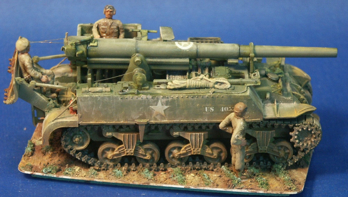
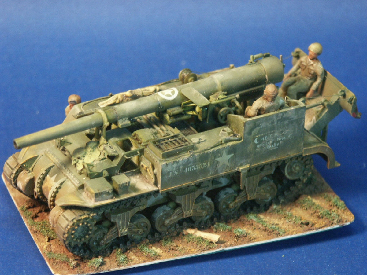
I could have used some fine resin crew figures, but chose to use the ESCI crew figures to show what they look like with the model. I find the ESCI figures to be misproportioned, rigid and some figure parts are very poorly detailed. The ESCI decals did not blend in with the model surface and we can see a raised ridge around some of them. One large decal marking "Cheerio!!!" broke and curled when applied and never looked right. Keep in mind that these ESCI decals are over 25 years old. Extra UM decals could have been used, but then we would not have known how the old ESCI decals behaved?
What we cannot see in this photo is a fine seam visible running atop the long gun barrel where the two barrel pieces (parts 1 and 2) were glued together. This seam was not visible before painting. A little model filler putty should have been used.
Conclusions In the box I always considered this a good model kit but with time, experience, and then the new UM Model kits to compare it with I saw some serious deficiencies. Overall the UM M12 model kit is a superior model and with one exception is easier to assemble and needs fewer scratchbuilt parts. References U.S. Self-Propelled Guns in Action, Armor Number 38, by Jim Mesko, Squadron/Signal Publications (1999) The Sherman Design & Development, Son of Sherman, Volume 1, softcover or hardcover book by The Ampersand Group Inc. (2013) Sherman Minutia website http://the.shadock.free.fr/sherman_minutia/index.html |
| Modeling the Sherman Tank in 1/72nd Scale |